Table of Contents
- Motivation
- Alarm Trigger PVs
- Alarm System Behavior
- Technical Overview
- Relational Database Setup
- Building the Tools
- Authentication and Authorization
- Alarm System Preferences
- Creating New Alarm Configuration, Bulk Modifications
- Putting it all together
- Alarm Server
- Alarm System JMS Message Types
- Alarm Tree View
- Alarm Table View
- Alarm Area Panel
- Annunciator
- JMS Alarm Log
This chapter introduces the CSS alarm system, specifically the “Best Ever Alarm System Toolkit” or BEAST. It was developed based on experience with the original EPICS alarm handler ALH combined with ideas from the book Alarm Management: Seven Effective Methods for Optimum Performance by B. Hollifield and E. Habibi, published by ISA in 2007.
The primary goal of the alarm system is simple:
Effectively help operators take the correct action at the correct time.
This is easier said than done! One way to accomplish this is to adopt the following guiding principles for an alarm handling philosophy:
-
Alarms are presented with guidance, related displays.
Lacking these, how can operators effectively react to an alarm?
-
Manageable alarm rate
The number of alarms should stay below about 150 per day. If the alarm rate gets much higher, the alarm system will no longer help operators take correct actions but instead overload them with information.
-
Operators will respond to every alarm.
This is a corollary to the previous item: Assuming a manageable alarm rate, operators are expected to respond to each alarm.
To implement such an alarm handling philosophy, a lot of effort needs to be put into defining useful alarms. Each alarm must have guidance, clearly describing what operators need to do in response to an alarm. There should not be any “bogus” alarms from systems that undergo maintenance, or that are currently irrelevant for the operation of the machine. Alarms must not “chatter”, causing unnecessary noise by going in and out of alarm. Operators need convenient access to the currently active alarms and their associated information. The alarm system tools described in the following try to help:
- Alarms are presented in user-selectable ways: Table of current alarms, sorted as desired, but also a tree-view, displaying all or only active alarms. In principle, additional views can be added.
- Each alarm is presented with additional information like guidance on how to handle the alarm. There are links to related operator screens, web pages, and other CSS tools.
- The alarm system configuration can be edited from within the alarm system user interface.
The alarm system handles the display of alarms and associated information. The triggers of alarms are simply Process Variables (PVs) in the control system, outside of the alarm system per se. The alarm system monitors such PVs, and a non-normal severity will trigger an alarm.
In some cases, existing control system PVs that already have suitable limits can be used as trigger PVs for the alarm system. In other cases, new PVs may have to be created to serve as alarm trigger PVs. For EPICS, this can be done on IOCs associated with the respective subsystem of the machine, or in soft IOCs that are purely meant to serve alarm trigger PVs. In any case, alarm trigger PVs must generate a non-normal severity like “MINOR” or “MAJOR” to trigger an alarm.
The alarm system will typically latch alarms. This means that the alarm trigger PV can return to OK, later re-enter the alarm state and so on, but the alarm system will only react when a PV enters an alarm state for the first time. Subsequently, the alarm system user interface will display the current state of the PV, but it will not trigger a new alarm nor issue another annunciation. This is meant to reduce noise from the alarm system.
Once operators are able to react to the original alarm, operators acknowledge the alarm, and the alarm trigger PV returns to normal, the alarm will clear. This is a typical time line:
- Alarm trigger PV X enters an alarm state, for example with “MINOR” severity.
- The alarm system will indicate a new MINOR alarm for PV X. If configured to do so, it will also perform a voice annunciation of the alarm.
- In a perfect world, the PV will stay in alarm until the underlying problem has been handled. In reality, the PV may briefly leave the alarm state, for example as a result of noise in a sensor. The alarm system will indicate this, but it still shows that there was a MINOR alarm with the time when it originally happened. As the PV re-enters a MINOR severity, there is no new alarm annunciation because this is considered part of the original alarm that has not been handled, yet.
- Hopefully, operators can address the underlying issue soon, the alarm trigger PV returns to a normal severity, and operators acknowledge the alarm.
- The alarm clears. It does not matter if the PV returns to normal, then operators acknowledge the alarm, or operators first acknowledge the alarm, then the PV returns to normal. The alarm will clear as soon as both conditions are met: PV returns to normal, alarm has been acknowledged.
Alarms may be configured not to latch, which means there is no need to acknowledge them. As soon as the alarm trigger PV returns to normal, the alarm will also clear. This mode of operation is primarily meant for alarm trigger PVs that already latch within the control system. An example would be an alarm trigger PV related to the “trip” condition of a device that requires a manual reset by operators to clear. That manual reset of the device is functionally equivalent to acknowledging the alarm, because an operator has noticed the condition and taken corrective action. The alarm trigger PV is unlikely to chatter because it latches until the device is reset. Requiring operators to acknowledge the alarm in addition to resetting the alarm trigger PV would cause unnecessary work.
One might be tempted to configure frequent alarms as non-latching to lessen the load on operators who get tired of acknowledging such a nuisance alarm. Overall, however, it is better to re-engineer such alarms. Add a filter to avoid alarms from brief occurrences of the symptom. Find a way to alarm on a precursor of the frequent alarm, allowing operators to avoid running the machine in a state that will later cause frequent occurrences of the nuisance alarm. Ideally, fix the underlying hardware or software to avoid the nuisance alarm altogether.

Fundamental to the operation of the alarm system is the
AlarmServer.
It reads the alarm system configuration from a relational database
and monitors alarm system trigger PVs.
Whenever a new alarm occurs, it informs alarm system user interfaces (GUIs)
via JMS. For alarms that should be annunciated, it will inform
annunciation tools via a designated JMS topic.
The Alarm Server performs the latching alarm behavior described in the previous section. As the severity of an alarm trigger PV changes, the server updates the GUIs via JMS about the current state of the PV, but it maintains the latched alarm state.
When operators acknowledge an alarm in the GUI, they are sending an acknowledge request via JMS to the Alarm Server. The server will in turn reply with the updated, eventually the cleared alarm state.
In addition to sending state updates via JMS, the Alarm Server also updates the alarm state in the relational database. This is done to allow newly started alarm GUI clients to obtain the initial state of all alarms. The persisted alarm state in the RDB also allows for Alarm Server restarts without loosing the alarm state.
Alarm GUI clients can change the alarm system configuration in the RDB. They use JMS to notify the Alarm Server and other GUI clients about the change, who then in turn read the updated configuration from the RDB.
As described, all alarm traffic passes through JMS: Alarm state updates, annunciations, acknowledgements, configuration changes. A generic JMS-to-RDB logger can thus capture all alarm traffic into an RDB for later review and anaysis, for example: What happened when? Which alarm was most frequent?
The RDB can hold more than one alarm system configuration. Each alarm configuration is identified by the name of its “Root” element, for example CCR for a Central Control Room configuration.
The Alarm Server and associated user interface clients must use the same alarm tree root. They will construct the names of JMS topics used to communicate by adding suffixes to the alarm tree root name. For example, with an alarm tree root of CCR, the server and clients will use the following JMS topics:
- CCR_SERVER: Used by the server to send alarm state updates to clients.
- CCR_CLIENT: Used by clients to send acknowledgement requests or configuration change notifications to the server.
- CCR_TALK: Used by the server to send annunciation messages to annunciators.
Exactly one alarm server needs to be running for each alarm system configuration, i.e. for each alarm tree root. Clients are bound to a specific alarm configuration via a preference setting that selects their alarm tree root name. Optionally, it is possible to enable users to change the alarm configuration at runtime via a selector in the Alarm Tree display.
The following is under development, not in operational use:
An alarm server can send information about alarms that stay un-acknowledged for a configurable time to a “GLOBAL_SERVER” alarm topic in JMS. A corresponding global alarm table user interface can display such alarms and allow operators to quickly switch to that alarm system configuration, where they then have access to the alarms guidance etc.
The use case for this is a central control room combined with several auxiliary, sub-system-specific control rooms. For example a cryogenic or conventional facility control room in addition to a bigger “main” control room. Most of the time, the auxiliary control rooms use their own alarm system configuration, specific to their needs, and all alarms are handled locally.
At night or on weekends, however, the auxiliary control rooms are not manned. At those times, alarms are not locally acknowledged, and after some timeout they will appear in the global alarm table of the main control room.
A listener to JMS messages on the GLOBAL_SERVER topic can also be used to trigger automated email notifications or send cell phone text messages in response to unhandled, i.e. un-acknowledged global alarms.
Before using the alarm system tools, you need to create the required table structure in your RDB,
see also Chapter 10, Relational Database (RDB).
Refer to the sources for the plugin org.csstudio.alarm.beast.
Its dbd subdirectory contains
schema definitions for MySQL, Oracle and PostgreSQL.
Pick the file that is appropriate for your RDB, and execute the commands listed in the file.
When done, you should have the alarm tables defined in your RDB. You have to use basic RDB administration skills to create a user and password for an account that the alarm tools can use to read and modify the alarm system configuration.
You need these command-line tools:
org.csstudio.alarm.beast.configtool/AlarmConfigTool.product
org.csstudio.alarm.beast.server/AlarmServer.product
For first tests, you can run both tools from within the Eclipse IDE as described in Chapter 4, Compiling, Running, Debugging CSS, the section called “Using the Eclipse IDE”, but note that you will have to provide command-line arguments to them. After first tests are successful, you can export them from the IDE as described in the same section.
Finally, you will need to include the alarm system client GUI (Alarm Table, Alarm Tree, Annunciator) into your end-user CSS product.
The Alarm Config Tool and the Alarm Server obviously need an account with write access to the alarm tables in the RDB because they modify the alarm configuration or state.
The alarm client GUI (Alarm Table, ...) is primiarily read-only, so a corresponding read-only RDB account would be sufficient. The GUI does, however, use CSS CSS authentication and authorization to allow a user to “Log On”, and qualified users are then permitted to modify the alarm configuration. It is in fact a prime feature of the alarm system that selected users can modify the alarm configuration on-line. For this to function, the CSS alarm GUI acutally requires an RDB account with write access. The CSS alarm GUI should therefore be provided with a write-access RDB account, and CSS authentication and authorization is then used to limit the use of that account within CSS.
The alarm GUI uses these Authorization IDs:
alarm_ack- Users with this authorization can acknowledge alarms.alarm_config- Users with this authorization can edit the alarm system configuration.
For initial tests, you can configure CSS authentication and authorization to use a “dummy” mode where every user can authenticate and gain these rights. Eventually, however, you might want to configure proper authentication and authorization. Refer to Chapter 13, Authentication and Authorization for details.
Most of the alarm system related preference settings
are explained and listed with their defaults in the file
preferences.ini of the plugin
org.csstudio.alarm.beast.
You will have to adjust the following, most important settings settings
for your site:
- URL, user, password and schema for connecting to the RDB that holds your alarm configuration. See the section called “RDB URLs and Schemata”.
- URL of your JMS server.
- Name of your alarm tree “Root”.
This is typically done by adding the site-specific settings
to the plugin_customization.ini file of
your product, see Chapter 6, Hierarchical Preferences.
For command-line tools like the alarm config tool you can also
create a file settings.ini as mentioned below.
Each alarm setup starts with a new, empty configuration in the RDB. The CSS alarm user interface will then allow to edit that configuration, but the initial, empty configuaration needs to be created in the RDB.
One way to create a new configuration is an SQL shell. Assume you want to create a configuration called “demo”, first check that it does not already exist:
SELECT * FROM ALARM_TREE
  WHERE NAME='demo' AND PARENT_CMPNT_ID IS NULL;
Find the next available component ID:
SELECT MAX(COMPONENT_ID) FROM ALARM_TREE;
Then create a new alarm tree root like this, remembering to use the next available component ID:
INSERT INTO ALARM_TREE (NAME, COMPONENT_ID)
VALUES ('demo', 1021);
While such direct SQL manipulations will work, it may be easier to
use the AlarmConfigTool.
The Alarm Config Tool can import alarm configurations from an XML file format.
A minimal, empty configuration with name “demo” would look like this,
usually saved to a file called demo.xml:
<config name="demo">
</config>
The sources for the plugin org.csstudio.alarm.beast.configtool
contain a schema file for the alarm configuration XML file format,
AlarmConfigurationSchema.xsd.
This can be used as a reference or to check an alarm configuration XML file
with XML tool before importing it via the alarm config tool.
To import such an XML configuration file into the RDB,
issue the following command,
assuming that you have a file settings.ini
that holds your site-specific RDB connection parameters:
AlarmConfigTool -pluginCustomization /path/to/my/settings.ini \
-import -root demo -file demo.xml
The config tool has more command-line options to list available configurations or to export a configuration to a file:
# Display all parameters
AlarmConfigTool -help

# List alarm tree root names
AlarmConfigTool -list

# Export alarm configuration to XML file
AlarmConfigTool -export -root demo -file demo.xml
While it is usually most convenient to edit an alarm configuration from the alarm client user interface, bigger changes to the alarm configuration are sometimes easier by exporting the existing configuration to an XML file, editing it, then re-importing it. The AlarmConfigTool is meant to handle such bulk-imports of the complete alarm configuration.
To perform partial changes of the alarm configuration, the AlarmConfigTool
has the -delete option to remove a subtree of the configuration.
You need to specify the complete path to the element that ought to be removed:
AlarmConfigTool -root demo -delete /demo/area1/system2
To remove a complete alarm tree, name the configuration and remove its root element:
AlarmConfigTool -root demo -delete /demo
If is possible to modify an existing configuration via the -modify command.
It will load an XML file and add newly listed items from the XML file to the alarm configuration,
or update the guidance messages, related displays etc. of existing items in the configuration.
It can not move items from existing locations to new locations in the tree, and you cannot add the
same trigger PV name to different sections of the tree.
For such wider ranging changes you will have to export, edit and then re-import the complete
configuration.
Note that the AlarmConfigTool only updates the database! If you are already using the alarm configuration, you should stop the AlarmServer and CSS alarm displays before performing such database updates, then start them back up when the database modifications are completed. If you update the alarm configuration from the CSS alarm GUI, all parts of the alarm system are notified about these changes so that they can update accordingly. Direct changes to the alarm database via SQL access or the AlarmConfigTool, however, go unnoticed by the AlarmServer and GUI clients, so you need to restart them.
So far, we described the alarm system in general as well as the setup of its infrastructure. In the following sections, we will describe how to run the alarm server and how to use the alarm client GUI.
Since this is a distributed system, it is important to remember its components:
- Control System: Often overlooked when you create your first alarm system test setup, you need for example an EPICS soft IOC that creates alarms.
- Configuration in RDB: Previous sections described the RDB table setup and how to use the Alarm Config Tool to create an initial alarm system configuration.
- JMS Server: See Chapter 12, Java Message Server how to start JMS. The Alarm Server and the Alarm GUI need to be configured with the URL of your JMS server to communicate.
- Alarm Server: Its operation will be described in the following sections.
- CSS Alarm GUI: Your CSS product needs to include the alarm tree and alarm table plugins to allow access to the alarm system. In addition, at least “dummy” authentication and authorization needs to be configured to permit changes to the alarm configuration from the client GUI. See Chapter 13, Authentication and Authorization.
The Alarm Server reads an alarm configuration, monitors the PVs of that configuration and notifies alarm clients about changes in the alarm state. It persists the alarm state in the RDB. For example, information about latched alarms is written to the RDB. When the Alarm Server is stopped and re-started, it will initialize from the RDB and learn about the previous state of all alarms. This way a previously latched alarm is recognized and not reported as a new alarm.
The Alarm Server is a command-line tool that is configured via Eclipse preferences, i.e. usually via a customization file like this:
AlarmServer -consoleLog -pluginCustomization /path/to/alarm_server.ini
The alarm server plugin org.csstudio.alarm.beast.server
includes an example plugin customization file plugin_customization.ini:
# Alarm System 'root', i.e. configuration name
org.csstudio.alarm.beast/root_component=Annunciator

# Alarm System RDB Connection
org.csstudio.alarm.beast/rdb_url=jdbc:mysql://localhost/alarm
org.csstudio.alarm.beast/rdb_user=alarm
org.csstudio.alarm.beast/rdb_password=$alarm
org.csstudio.alarm.beast/rdb_schema=ALARM

# Alarm System JMS Connection
org.csstudio.alarm.beast/jms_url=failover:(tcp://localhost:61616)
org.csstudio.alarm.beast/jms_user=alarm
org.csstudio.alarm.beast/jms_password=$alarm

# Alarm Server: Period for repeated annunciation of active alarms
org.csstudio.alarm.beast.server/nag_period=00:15:00

# Channel Access
# Network traffic can be optimized by only monitoring ALARM updates,
# but that has the disadvantage that formulas will also only
# react to input variable changes when their alarm severity differs.
# So unless this optimization is necessary, it's best to use VALUE updates
org.csstudio.diirt.util.core.preferences/diirt.ca.pure.java=true
org.csstudio.diirt.util.core.preferences/diirt.ca.dbe.property.supported=false
org.csstudio.diirt.util.core.preferences/diirt.ca.monitor.mask=VALUE
org.csstudio.diirt.util.core.preferences/diirt.ca.addr.list=127.0.0.1
org.csstudio.diirt.util.core.preferences/diirt.ca.auto.addr.list=true

# Logging preferences
org.csstudio.logging/console_level=CONFIG
org.csstudio.logging/jms_url=
For more on the Eclipse preference mechanism, see Chapter 6, Hierarchical Preferences.
If you started the Alarm Server successfully, its terminal output should resemble this, displaying the JMS topics used by the alarm server:
Alarm Server 3.0.0
Configuration Root: demo
JMS Server Topic:   demo_SERVER
JMS Client Topic:   demo_CLIENT
JMS Talk Topic:     demo_TALK
JMS Global Topic:   GLOBAL_SERVER
Read 50003 PVs in 1.69 seconds: 29589.0 PVs/sec
The alarm server communicates with the alarm GUI via JMS messages described in the following section. The alarm GUI will either show alarm updates, or it will indicate a server timeout if the alarm server does not communicate. To debug the setup, the JMS Monitor (Chapter 33, JMS Monitor - org.csstudio.debugging.jmsmonitor) can be used to monitor the JMS server, client and talk topics. The JMS server topic should show alarm state changes or at least periodic IDLE messages.
The Alarm Server sends this type of JMS MapMessage
for alarm state changes:
TYPE: Set to “alarm” to identify as alarm message.TEXT: STATE in normal mode, STATE_MAINTENANCE in maintenance mode.CONFIG: Name of the alarm configuration, i.e. alarm root.NAME: PV name that has changed alarm stateCURRENT_SEVERITY: Current severity of the PV.CURRENT_STATUS: Current status of the PV.SEVERITY: Alarm severity of the PV. For latched or acknowledged alarms, this can differ from the current severity.STATUS: Alarm status of the PV.EVENTTIME: Time of the original alarm, i.e. when SEVERITY became active.APPLICATION_ID: AlarmServer.HOST: Host name running the alarm server.USER: Name of user who is running the alarm server.
In the absense of alarm state changes, the Alarm Server sends an IDLE message, by default every 10 seconds. If the alarm client GUI does not see any message from the alarm server for twice the IDLE period, it declares a server timeout.
TYPE: Set to “alarm” to identify as alarm message.TEXT: IDLE in normal mode, IDLE_MAINTENANCE in maintenance mode.CONFIG: Name of the alarm configuration, i.e. alarm root.APPLICATION_ID: AlarmServer.HOST: Host name running the alarm server.USER: Name of user who is running the alarm server.
Alarm clients send this message to acknowledge or un-acknowledge an alarm:
TYPE: Set to “alarm” to identify as alarm message.TEXT: ACK respectively UN-ACK.CONFIG: Name of the alarm configuration, i.e. alarm root.NAME: PV nameAPPLICATION_ID: CSS.HOST: Host name running CSS.USER: Name of user who is running CSS.
Alarm clients send this message to enable or disable maintenance mode:
TYPE: Set to “alarm” to identify as alarm message.TEXT: MODE.VALUE: MAINTENANCE or NORMAL.CONFIG: Name of the alarm configuration, i.e. alarm root.APPLICATION_ID: CSS.HOST: Host name running CSS.USER: Name of user who is running CSS.
After modifying the alarm configuration, alarm clients send this message to the server:
TYPE: Set to “alarm” to identify as alarm message.TEXT: CONFIG.CONFIG: Name of the alarm configuration, i.e. alarm root.NAME: Path to the modified configuration item.APPLICATION_ID: CSS.HOST: Host name running CSS.USER: Name of user who is running CSS.
Note that other clients are also listening to this message, so the server as well as other clients will react by updating their configuration from the RDB. If the path contains a specific configuration item like “/area/system/subsystem/pv”, only the configuration for that item needs to be updated from the RDB. If the path is empty, a bigger change to the configuration means that the complete alarm configuration needs to be updated from the RDB.
The Alarm Tree
display can be opened from the menu
CSS, Alarm, Alarm Tree.
It is the primary display for viewing and configuring the complete
alarm tree.

The alarm tree displays the hierarchical structure of the alarm system. Alarms are arranged into
- Areas - Top-level elements of the alarm hierarchy.
- Systems, Subsystems - Below the top-level areas, there can be multiple levels of systems and subsystems to organize your alarm configuration.
- PVs - Finally, the alarm trigger PVs generate actual alarms.
It is suggested to use physical areas, because that way the general localization of an alarm in the machine is obvious. The systems or subsystems could for example be Vacuum or Cooling, i.e. again physical systems of your machine.
When configuring the guidance or related displays of an item in the alarm configuration, this will affect all entries below the respective item. For example, when adding a display link to an area, this link will be available for each system, subsystem and PV below that area. This way it is easy to assign overview displays for an area, or add guidance with contact information for a system to those elements in the alarm tree without need to duplicate the information for each PV.
The alarm tree needs to be used to add, rename or remove entries of the alarm configuration. To operators, the alarm tree can be useful if many alarms are active, because its hierarchical view can allow operators to identify the affected areas or subsystems better than a plain list of alarms could do.
For details on how to use the alarm tree, refer to its online help.
In an ideal operational setup, there are only very few alarms. If alarms trigger, they may be from very different areas of the machine. In this scenario, operators are often not interested in all the possible alarms as they are displayed by the Alarm Tree. Instead, they only need to know the currently active alarms.

The Alarm Table display is the primary operator interface to the alarm system in an operational setup for a machine that is generally running fine. Most of the time, the alarm table will be empty, because there are no alarms. If alarms occur, the alarm table allows operators to inspect them quickly.
For details on how to use the alarm table, refer to its online help.
The Alarm Area Panel can be used as a top-level display of the current alarm state. A preference setting of the panel is used to configure which level of the alarm tree hierarchy it should display.
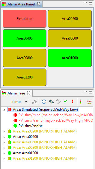
It will typically be used to display the first level of the alarm hierarchy, that is all “Area” components of the alarm tree. For each area, it displays the name, coloring the panel to indicate the alarm state of that area as in Figure 14.4, “Alarm Area Panel”.
The tool can also be used to display a single panel with the alarm state of the overall alarm tree, i.e. the root element, by configuring it to use level 0 of the alarm tree hierarchy. When set to level 2 of the alarm tree, it will display all “System” components. With level 3 it would display all “Sub-System” components, but this and higher alarm tree components are not useful in practice.
For details on how to use the alarm table, refer to its online help.
This tool performs voice annunciation of alarms.
It usually listens to the JMS ..._TALK topic
associated with an alarm tree configuration and speaks
received alarms to the operator.
The annunciator can be configured to listen to one or more topics.
It will typically listen to one specific alarm tree ..._TALK topic
like CCR_TALK, but in principle it can listen to talk topics
from multiple alarm tree configurations.
It could also annunciate messages that are sent to JMS topics by means other
than the alarm system.
The annunciator is available in two forms:
- Eclipse View: The Annunciator view can be opened from the CSS Alarm menu
as long as your CSS product includes the plugin
org.csstudio.alarm.beast.annunciator. - Headless Application: The Annunciator application is started from the command line.
To create the headless executable, export the
Annunciator.productproduct from the annnuciator plugin. The headless annunciator application is also referred to as JMS2SPEECH.
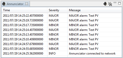
The annunciator view is convenient for use within CSS and has the added advantage of displaying a list of recently received alarm messages. It will, however, stop annunciating as soon as the annnuciator view is closed or hidden. It is therefore important to keep the annunciator view visible to assert that it can perform annunciations.
The annunciator view offers two buttons it its toolbar: One to temporarily silence alarms, the other to clear the list of past annunciations.
The headless Annunciator application needs to be launched separately from the CSS user interface, but has the advantage that it will annunciate even when the CSS user interface is closed. For end users, the annunciator view may be more convenient, but in a control room it is suggested to run at least one copy of the headless Annunciator application.
The annunciation of a message takes some time. When several messages are received for annunciation, they are ordered by their severity. When too many messages arrive, especially from the alarm system, there is usually little use in annunciating them because the bigger message is: There are MANY messages, do something about it! If the queue length exceeds a configurable threshold, the queue is therefore cleared and only a single “There are ... more messages” statement is announced.
Either version of the annunciator is configured via preferences.
Refer to the preferences.ini file of the annunciator
plugin or the CSS preference GUI when using the view to configure the following,
where the first two are essential for the operation of the tool:
- URL of the JMS server from which the annunciator receives messages.
- JMS topics to which it listens. This is a comma-separated list like
CCR_TALK, Demo_TALK - Translations file. This file can be used to provide pronunciation help. Refer to the online help for details.
- List of message severties, separated by comma, ordered by priority (highest first) to define how the annunciator should prioritize when receiving several concurrent messages.
- Threshold for ignoring flurry of messages. When more than this number of messages queue up, a shorter “There are .. more messages” statement is annunciated.
- The number of messages kept in the Annunciator View display of recent messages.
Also note the separate preferences of the speech library mentioned below.
Fundamentally, messages are annunciated as received. The alarm server will usually include the alarm severity in the message. For example, an alarm with description
Low Water Pressure
will be annunciated as
"MINOR alarm: Low Water Pressure"
when it enters a MINOR alarm state.
If an alarm description starts with an asterisk as in
*Low Water Pressure
the alarm server will use the description as given. It will not prefix it with the alarm severity. A PV with above Description thus results in just announcing
"Low Water Pressure"
In addition, descriptions starting with an asterisk can include the following formatting elements:
- The text
{0}is replaced with the current alarm severity. - The text
{1}is replaced with the value of the trigger PV that caused the alarm.
For example, a PV with description
*{0} alarm: Low Water Pressurewould again result in an annunciation
"MINOR alarm: Low Water Pressure"
The effect would be the same as having used the default annunciation
format without *.
By using the * format, however, you can also use descriptions like
*{0} water alarm, level is {1} gallonswhich will result in an annunciation similar to
"MINOR water alarm, level is 3.142 gallons"
The format elements can be in any order. For example, the value can be used before the alarm severity. The description
*Water below {1} gallons, {0} alarmwill result in an annunciation similar to
"Water below 3.142 gallons, MAJOR alarm"
We mentioned that messages will be suppressed when too many messages arrive. Very important messages can be prefixed with an initial exclamation mark:
!Running low on cookies
Such messages will always be annunciated and not be dropped when there too many other messages.
When combining the formatting element *
and the ! to prevent suppression, note the required order.
You have to use
*!My description ...
i.e. first the *, then the !.
The annunciator uses the plugin
org.csstudio.utility.speech
for the text-to-speech conversions.
That plugin can be configured to use either
the pure Java FreeTTS library that it provides,
an external tool,
or a UDP server.
Refer to the preferences.ini
of the utility.speech plugin for available options.
When selecting the external tool, a program called say
is expected to be found on the PATH.
It must accept the text to annunciate as a command line argument.
On Mac OS X, such a say command is already part of the operating system.
On Linux computers, one can often use the following shell script to invoke
festival:
#!/bin/sh
#
# Example 'say' script for Linux

echo "$@" | festival --tts
When selecting the UDP server, you also need to configure the hostname
or boradcast address and port number of the UDP server, again refer to
the preferences.ini of the utility.speech plugin.
The UDP server will receive each annunciation as a seprate UDP packet.
The alarm server will issue one annunciation for each new alarm that is configured to be annunciated. If operators miss an annunciation, we generally assume that they were distracted by more important tasks. Once they have time, they can inspect the alarm GUI for new alarms, for example from the time-sorted alarm table, or consult the list of recent messages in the annunciator.
Annunciations are not repeated, because in general we try to minimize the noise generated by the alarm system. Sometimes, however, it can be useful to remind operators that there were alarms that they might have missed.
The nag_period configuration parameter of the alarm server
instructs the alarm server to generate periodic voice annunciations
"There are ... active alarms"
whenever there are active, that is un-acknowledged alarms.
The default nag_period of 00:15:00 causes
this annunciation to be performed every 15 minutes.
Whenever operators acknowledge or un-acknowledge an alarm, or change the alarm configuration, or if there is a different annunciation, the timer for active alarm reminders is reset. In normal operation of the alarm system where operators acknowledge alarms, or while there are other annunciations that we assume are heard by operators, there will therefore be no reminder. On the other hand, if operators have not interacted with the alarm system, not acknowledged any alarms, now were there any other new annunciations, yet there are still active alarms, this reminder will help operators every 15 minutes to notice that something happened that they might have missed.
The active alarm reminders can be disabled by configuring the
nag_period as 0.
The JMS2RDB tool described in Chapter 35, RDB Logging - org.cstudio.logging.jms2rdb can be used to log all alarm traffic to the RDB. This way, detail of alarm state changes and operator acknowledge actions will be available in the CSS log for later analysis. The message history display described in Chapter 31, Message History Browser - org.cstudio.alarm.beast.msghist allows direct access to the log, although it can be time consuming the decode the raw messages.
At the SNS, a JSP-based collection of reports can display how many alarms were active over the last days or weeks, which alarms represent the “Top 10” of the most frequent alarms, and how one alarm behaved in detail, including histograms of alarm durations.
This reporting package, however, is currently part of a bigger, more SNS-specific reporting package. Contact Kay Kasemir if you are interested in collaborating on a more portable version of these reports.